
Six-Axis Force/Torque Sensors Explained: How They Measure and How to Read the Datasheet
Source: https://sourcebotics.com/guides/six-axis-force-torque-sensors-explained/
Short answerA six-axis force/torque sensor measures three forces and three moments with strain gauges on a machined body, then converts the readings through a calibration matrix. Choose the range from the forces and moments at your mounting point, then compare accuracy, crosstalk, overload capacity, interface and sampling rate under the manufacturer's stated conditions.
How a six-axis sensor measures load
The sensor body is a machined metal structure, often a hub connected to an outer ring by beams. When load is applied, the beams bend slightly. Strain gauges bonded to the beams change resistance with that bending, and are wired into Wheatstone bridges whose output voltage changes with strain. A typical design has six or more bridge channels.
No single channel corresponds to one axis. A force along X also bends beams that contribute to other channels. The manufacturer applies known loads during calibration and computes a decoupling matrix that converts the channel readings into Fx, Fy, Fz, Mx, My and Mz. Digital sensors apply this matrix internally; analog sensors supply it for your software to apply.
Reading the measuring range
Datasheets list a range for each force and moment axis. The moments matter as much as the forces: a tool that extends from the sensor turns a modest force into a large moment. Calculate the worst-case force and moment at the sensor face, including tool weight, acceleration and contact forces, then choose the smallest range that covers them with margin. A larger range than necessary reduces the resolution of the forces you care about.
Accuracy figures and what they mean
Accuracy, nonlinearity, hysteresis and crosstalk are usually stated as a percentage of full scale. Crosstalk describes how much load on one axis appears as a reading on another. Because these figures scale with the range, a small percentage of a large range may still be larger than the force you need to resolve.
Temperature also matters. Strain gauges and the sensor body respond to temperature changes, so manufacturers state a compensated temperature range. In practice you will zero the sensor after warm-up and periodically during long tasks.
| Datasheet item | What it tells you | How to use it |
|---|---|---|
| Force and moment range | Loads where stated accuracy applies | Cover worst-case loads at the sensor face with margin |
| Accuracy / nonlinearity | Deviation from ideal output, % of full scale | Convert to newtons or newton-metres for your range |
| Crosstalk | Error leaking between axes, % of full scale | Critical when one axis is loaded far more than others |
| Overload capacity | Load survived without damage | Size for collisions, tool changes and handling |
| Sampling rate | How often readings are produced | Match to your force-control loop rate |
| Interface | Analog bridge or digital bus output | Check controller support and cabling |
| Mass and dimensions | Added load and stack height at the flange | Subtract from robot payload and reach |
| Ingress protection | Protection against dust and water | Match to cleaning and environment |
Overload, collisions and handling
The measuring range is where accuracy applies; overload capacity is what the sensor survives. Applications with impacts, manual guiding or tool changes need a generous overload rating. Many sensors also include mechanical stops that protect the gauges, and some offer overload indication in the digital output.
Analog or digital output
Analog sensors output small bridge voltages and need an amplifier and data acquisition system, plus the decoupling matrix in software. They allow high sampling rates and flexible signal chains. Digital sensors integrate the amplifier and matrix and output through EtherCAT, Ethernet, CAN or RS-485, which simplifies integration and cabling. Confirm that your robot controller supports the bus and that drivers or examples exist for your software.
Mounting and integration
The sensor sits between the robot flange and the tool, so it adds mass and height, which reduces the robot's usable payload and changes the tool centre point. Adapter plates for common robot flanges are often available. Cable routing must avoid strain on the connector during motion. After installation, compensate the tool's weight and centre of mass in software so that only external forces remain.
Checklist for a force/torque sensor inquiry
- Robot model and tool flange.
- Worst-case forces and moments at the sensor face.
- Smallest force you need to resolve.
- Overload scenarios: collisions, manual guiding, tool changes.
- Interface and sampling rate required by your controller.
- Environment: temperature range, dust, water and cleaning.
- Documents: datasheet, calibration certificate, drawing and software examples.
Sources
FAQ
Do I need a six-axis sensor, or is a single-axis load cell enough?
If the load always acts along one known direction, a single-axis cell can be enough. Assembly, polishing, guiding and contact-rich tasks involve forces and moments in several directions and need six axes.
Why does my sensor reading drift?
Temperature changes, cable movement and creep in the structure cause drift. Zero the sensor after warm-up and before force-critical steps, and route cables with strain relief.
What does a calibration certificate show?
The applied reference loads, the measured outputs, the resulting matrix and the accuracy achieved. Ask for it with the shipment.
Planning a robotics purchase? Share the quantity, configuration and destination so we can check fit, availability and quote requirements.
Request a quote— The Sourcebotics sourcing desk
Related products
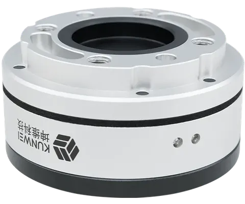
- Measurement axes
- Fx, Fy, Fz, Mx, My, Mz
- KWR75A ranges
- Fx/Fy/Fz: 50 N; Mx/My/Mz: 2 N·m
- KWR75B ranges
- Fx/Fy/Fz: 200 N; Mx/My/Mz: 8 N·m
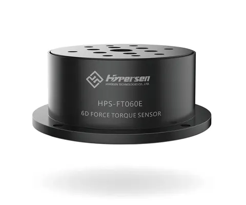
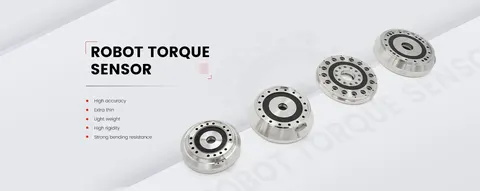
- Measurement axes
- Fx, Fy, Fz, Mx, My, Mz
- M4313M4E
- 250 N / 24 N·m; Ø95 mm; EtherCAT output
- M4313M4B
- 250 N / 24 N·m; Ø95 mm; Ethernet TCP/IP output
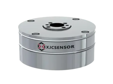
- Measurement axes
- Fx, Fy, Fz, Mx, My, Mz
- D62-H27-C dimensions
- Ø62 × 27 mm
- D62-H27-C range options
- 100 / 200 / 500 / 1,000 N paired with 2 / 4 / 10 / 20 N·m